aaronm
2923

RdM 101
Here's a schematic of how I see the RdM Mechanism. I cannot vouch for it yet, and i apologize for both the horrible coloring, and the poorly-drawn gears.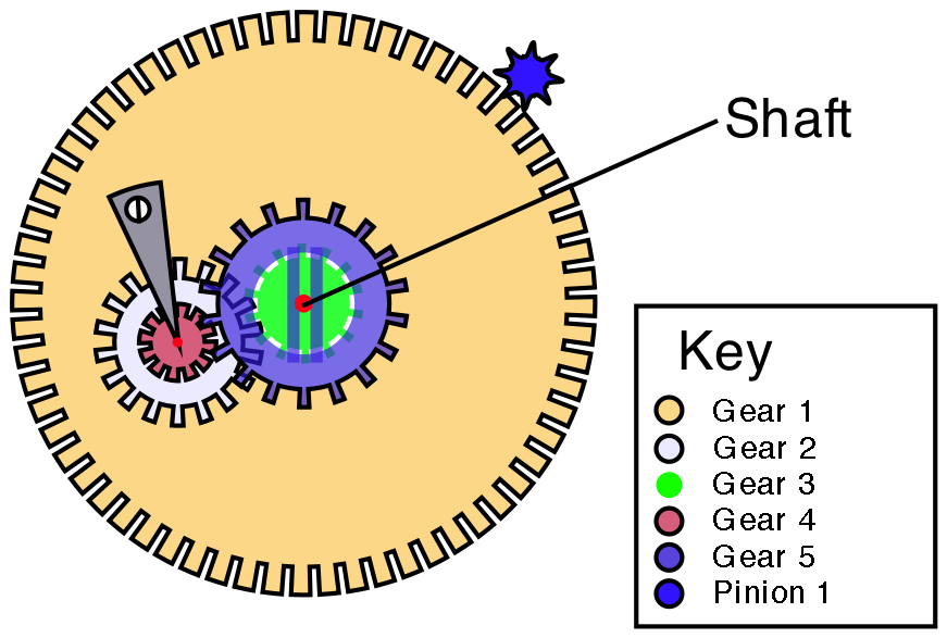
The gray thing is the cock that holds gears 2 and 4 to gear 1, it doesn't look anything like I drew it, my way is simpler to draw, theirs is much flatter. The red dots are pivots.
Atop gear 5, and attached to it, is a tiny little pinion gear that drives the RdM hand, I haven't drawn that one in yet.
So the flow of power is, in winding:
pinion 1 is locked, so gear one is stationary.
the ratchet wheel (silver wheel on the back of the barrel, engaged by the click) turns a pinion I can't see which is attached to gear 3.
gear 3 turns gear 2, which is attached to gear 4
gear 4 turns gear 5, which moves the hand.
so the flow of power is gear 3->gear 2=gear 4->gear 5
In running
gear 3 is locked.
pinion 1 turns gear 1.
this causes gear 2 to rotate, since it is being moved around gear 3, which is locked in place.
gears 2 and 4 are still attached, so a rotating gear 2 rotates gear 4, which rotates gear5 moving the hand. the reason this works is that the ratios between gears 2 and 3, and 4 and 5 are different, slightly. Think of this simple example:
Gear 2 has 6 teeth
Gear 3 has 6 teeth
Gear 4 has 4 teeth
Gear 5 has 8 teeth
as gear 2 makes one complete revolution about gear 3, it rotates a single time (6 teeth to 6 teeth)
which causes gear 4 to rotate once. This only causes gear 5 to make 1/2 rotation. (4 teeth to 8 teeth)
The reason this works is the locking action of Pinion 1 on Gear 1 versus the locking of Gear 3. A simple change of gear 1 locked in place, versus gear 3 locked, changes the gearing ratio.
My next plan is to try and unwrap the gear stack, but it'll take some time.
Aaron
ps 2 notes,
1. gear 5 is not attached to the labeled shaft, it uses it as an object to pivot about, regardless of whether it is rotating.
2. That shaft is a bad mother.....

Breguet La Tradition 7027 labelled movement (back)

Part I and II to save , IMO!


An excellent job!!!!
I will leave the automatic La Tradition for you…
Thanks dear friend...
Worth the wait...
Yes, a varient on planetary gears
Planetary Gears 101
RdM 101
a bit of help on the keyless works.