Patience Please – Measurements on a Precision Pendulum
DonCorson

I have recently been surprised by a new insight I have had working on my first pendulum clock. It is again something that can be explained with the help of that enigmatic parameter of oscillating systems known as the quality factor Q.
I have discussed the quality factor before here, as I presented a lecture by Douglas Bateman about the quality factor and the first results measured on my own pendulum clock. Since those first results I have changed the weight by making it smaller and also heavier (filling with lead) which has slightly increased the Q of the pendulum, I assume mostly due to less air resistance from the smaller size.
The simplest method to measure Q is to excite the system and then let the oscillations decay. The Q of the system is the number of periods of the oscillator needed for the amplitude of the oscillation to reach 50%, or one half, multiplied by 4.53. The graph in the article above shows the measurment data.
Another method of measuring Q is to measure the system response to a step change in the excitation. For example going from an excitation of 1 to an excitation of 2. This is an evident case for all electrical engineers as Q is related to the well known system time constant tau. So it is possible to measure the Q of a running system by changing the excitation, measuring the system response and then calculating tau and Q.
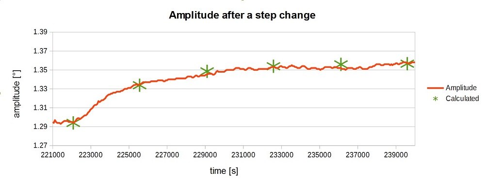
More or less by accident I recently did this on my pendulum. I only noticed this when I was looking at the measurement data afterward. I had made an adjustment to the gravity arm that gives the impulse to the pendulum. That adjustment had resulted in a small increase in the amplitude. This was exactly the step change in excitation needed to measure tau. Below we see the measurement.
The time in seconds is on the bottom axis advancing from left to right. On the left axis is plotted the amplitude of the pendulum movement. The red line is the measured data, each data point the average amplitude of the 30 swings made during one minute. The adjustment was made at about the time 222000 seconds, at the first green star from the left. We can see how the amplitude rises in a nice exponential curve as we expect. The green stars are the calculated values at 1tau, 2tau, etc, the last at 5 tau where the calculated value is 99.2% of the end value. As we can see these values calculated using a Q of 11'000 fit very nicely with the measured values confirming the measurement using the decaying oscillation.
And what was so surprising about this calculation ?
Well, the patience we need when doing any measurements on such a high precision timekeeper. The calculated value of tau is 3501 seconds, almost an hour. For the oscillation of the pendulum to reach 5tau, the value accepted in engineering as “reaching the end value” as it is less than 1% error, we need to wait 17505 seconds or 4 hours and 51 minutes. Before that time the system is still in a dynamic state and any measurement will be that of an intermediate state between the old and the (coming) new value.
So when regulating your precision pendulum be sure to bring lots of patience along with you. What you change now will only give meaningful results in several hours. Here I have only shown the amplitude, but as the rate is also very slightly dependent on the amplitude, this also holds for the rate.
I know you are thinking “and where are the pictures of the pendulum?”. Well it is really not in a state that I like to show, but here are some anyway.
The pendulum weight ready for filling with lead. Said lead, in the bucket seen behind, in the form of automotive wheel balancing weights that I melted down.

Here we see the pendulum rod of quartz glass with the lead filled weight, the impulsing surface attached to the rod (only the right side is used, I made it left and right symetrical just to be pretty), the gravity arm at the right which gives an impulse once every 30 seconds and below the weight the optical barriers used to determine the position of the pendulum for the impulse and to measure the rate and amplitude.
The display on the measurement computer shows the rate, amplitude, temperature, barometric pressure and humidity. Dangling from the measurement compi is the SD card used to log all the measured data. Between the pendulum weight and the optical barriers on the pendulum is the temperature compensation in the form of a brass tube, my present construction site. After that is calibrated and working correctly I will add barometric compensation.

Who knows what new surprises I will find, but one thing is sure… I will need lots of patience.
This message has been edited by DonCorson on 2016-01-04 13:08:24
I have discussed the quality factor before here, as I presented a lecture by Douglas Bateman about the quality factor and the first results measured on my own pendulum clock. Since those first results I have changed the weight by making it smaller and also heavier (filling with lead) which has slightly increased the Q of the pendulum, I assume mostly due to less air resistance from the smaller size.
The simplest method to measure Q is to excite the system and then let the oscillations decay. The Q of the system is the number of periods of the oscillator needed for the amplitude of the oscillation to reach 50%, or one half, multiplied by 4.53. The graph in the article above shows the measurment data.
Another method of measuring Q is to measure the system response to a step change in the excitation. For example going from an excitation of 1 to an excitation of 2. This is an evident case for all electrical engineers as Q is related to the well known system time constant tau. So it is possible to measure the Q of a running system by changing the excitation, measuring the system response and then calculating tau and Q.
More or less by accident I recently did this on my pendulum. I only noticed this when I was looking at the measurement data afterward. I had made an adjustment to the gravity arm that gives the impulse to the pendulum. That adjustment had resulted in a small increase in the amplitude. This was exactly the step change in excitation needed to measure tau. Below we see the measurement.
The time in seconds is on the bottom axis advancing from left to right. On the left axis is plotted the amplitude of the pendulum movement. The red line is the measured data, each data point the average amplitude of the 30 swings made during one minute. The adjustment was made at about the time 222000 seconds, at the first green star from the left. We can see how the amplitude rises in a nice exponential curve as we expect. The green stars are the calculated values at 1tau, 2tau, etc, the last at 5 tau where the calculated value is 99.2% of the end value. As we can see these values calculated using a Q of 11'000 fit very nicely with the measured values confirming the measurement using the decaying oscillation.
And what was so surprising about this calculation ?
Well, the patience we need when doing any measurements on such a high precision timekeeper. The calculated value of tau is 3501 seconds, almost an hour. For the oscillation of the pendulum to reach 5tau, the value accepted in engineering as “reaching the end value” as it is less than 1% error, we need to wait 17505 seconds or 4 hours and 51 minutes. Before that time the system is still in a dynamic state and any measurement will be that of an intermediate state between the old and the (coming) new value.
So when regulating your precision pendulum be sure to bring lots of patience along with you. What you change now will only give meaningful results in several hours. Here I have only shown the amplitude, but as the rate is also very slightly dependent on the amplitude, this also holds for the rate.
I know you are thinking “and where are the pictures of the pendulum?”. Well it is really not in a state that I like to show, but here are some anyway.
The pendulum weight ready for filling with lead. Said lead, in the bucket seen behind, in the form of automotive wheel balancing weights that I melted down.
Here we see the pendulum rod of quartz glass with the lead filled weight, the impulsing surface attached to the rod (only the right side is used, I made it left and right symetrical just to be pretty), the gravity arm at the right which gives an impulse once every 30 seconds and below the weight the optical barriers used to determine the position of the pendulum for the impulse and to measure the rate and amplitude.
The display on the measurement computer shows the rate, amplitude, temperature, barometric pressure and humidity. Dangling from the measurement compi is the SD card used to log all the measured data. Between the pendulum weight and the optical barriers on the pendulum is the temperature compensation in the form of a brass tube, my present construction site. After that is calibrated and working correctly I will add barometric compensation.
Who knows what new surprises I will find, but one thing is sure… I will need lots of patience.
This message has been edited by DonCorson on 2016-01-04 13:08:24
Comments:

BDLJ December 21st, 2015-14:26
That final photo is superb, Don. The mix of old and new technologies. The precise and the haphazard. Quartz glass and Plywood. You've shown your data logging, but what are you using as the time reference?

DonCorson December 22nd, 2015-04:39
I don't really relish posting photos at this stage of the work 'though As in all other engineering development, it is a big help knowing what has to be precise and what can be done with simpler means. So I am using a thick plywood backboard where I can run screws in anywhere to hold things. That is convenience at this point ...
0-10-2
Load More Comments
Next Article
DonCorson
A David Walter Double Pendulum Clock – Part 15, The Sidereal Train
DonCorson
David has finished the sidereal conversion train. As you know this train is used to convert the mean solar time that we usually use, based on the position of the sun, to astronomical time, based on the position of the stars. Following is David's description of the work. For those of you who didn't see the earlier installments of this series, you can catch up by looking here: - Installment 1 – Introduction and Cutting out the plates - Installment 2 – Making the Barrel - Installment 3 – The Suspension - Installment ...
© 2017 - WatchProZine